Patent No.:Â WO/2008/103129
Abstract:
Description:
The present invention is a device both self sufficient (self feeding) and producing ready to use electric energy, starts to operate with the initial electrical energy received from accumulator or similar source of energy, transferring the magnetic field generated in first bobbin to second bobbin through a frequency stabilizer, after rhythmically stabilizing the magnetic field occurred between the bobbins; converts the independent energy -received by the second bobbin from the air- to electric energy.
Today electric energy can be generated by using various kinds of technologies. In order to summarize some of them; electric energy can be generated through dams, from the motion of waves, by nuclear power plants, by using solar energy, fuel oil, hydroelectric power plants and similar areas through using various technologies. There are different advantages and disadvantages among these various techniques used for generating electric energy. The general purpose of all these techniques is to generate energy cheaper and faster by providing high efficiency. The present invention is improved through using different technologies of today, by less costly way and without harming the nature, and using a very different technique from the above mentioned (present techniques used today).
The present invention receives energy externally only at first starting phase. This mentioned energy can be easily generated from a small accumulator or chargeable battery or similar sources. 1 -2 seconds after the device is started, the power switch at the energy input of the device cuts the external electric (from accumulator or similar source of energy) off by generating electric energy. A very few part of this electric energy generated is used by the device to feed itself and the most part is discharged ready to be used. As long as the device is not shut down or no problem occurred inside, the device generates energy consistently. By recent technology, there is no device similar to the present invention producing energy consistently by feeding itself.
In order to maintain the device to generate electric energy consistently, two circuits are designed inside the device.
First circuit; consists of time relay switch, capacitor, points, high frequency generator, first filter, first bobbin, first frequency adjuster (this circuit is displayed with bold line on the figure)
Second circuit; consists of second filter, frequency stabilizer, second bobbin, second frequency adjuster.
First circuit is designed for generating electricity by transferring the electro magnetic field occurred at the first bobbin with the electric energy received from the independent initial power supply, to second bobbin. And as the second circuit; Due to the high magnetic field received from the first bobbin, there occurs a magnetic field difference between the bobbins. The magnetic field difference occurred between the second bobbin and first bobbin stabilized by the help of frequency stabilizer within this circuit line. As stabilizing the magnetic field difference by the help of frequency stabilizer, this circuit line also converts the energy which is moving independently in the air at the second bobbin designed within this line to electric energy. This electric energy formed by the second bobbin adjusts the necessary frequency (220 V – 50 Hz or 110 V – 60 Hz) for use, by the help of second frequency adjuster designed at the bobbin output. This generated electric energy is transferred to the intended usage area via exit points. Through the circuit cables connected to the exit points, the device feeds itself with the generated electric energy. This mentioned process eventuates 1 -2 seconds after the device is got started. After this process, the time relay power switch designed at the input of the device breaks the initial energy supply. After this stage, the device generates the energy independently.
The present invention is designed as single phase and as the phase number is desired to be increased, the bobbin number shall also be increased for each phase. Depending on the number of bobbins, the capacities of other parts used in the device are increased symmetrically.
It is possible to obtain energy in desired amounts of KW from the device. It is necessary to increase the capacity of the parts depending on the value of the electric energy. The figures related to the invention are given enclosed; from the related figures:
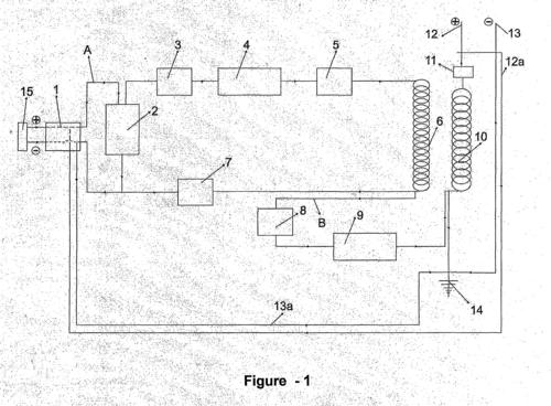
Figure 1- Schematic view of the present invention
The parts related to the invention are given numbers and the explanations responding these numbers are as follows:
1- Power switch 2 – Capacitor
3- Points (as distributor of an engine)
4- High frequency generator
5- First filter
6- First bobbin
7- First frequency adjuster 8- Second filter
9- Frequency stabilizer (adjuster)
10- Second bobbin
11- Second frequency adjuster
12- Exit (phase) (positive) 12a- Positive transformation cable
13- Exit (neutral)
13 a- Negative transformation cable
14- Neutral (grounding) 15 – Initial power supply A- First circuit cable B- Second circuit cable
The operation of the present device is explained as below, giving reference to the parts’ numbers through the figure enclosed.
Energy and frequency circuit on the first circuit (A) Opening the power switch, the user gives the electric energy received from the initial energy supply (15) to the first circuit cable (A). Being loaded with the electric energy received from the energy supply (15) the capacitor (2) serves as a pump, and provides the points (3) to give electric to the high frequency generator (4). High frequency generator (4) transfers the high amount of frequency it generated to the first filter (5). First filter (5) stabilizes the frequency received from the high frequency generator (4) and regularly transfers to the first bobbin (6). Creating a magnetic field around itself with the high frequency regularly received from the first filter (5); first bobbin (6) transfers it to the second bobbin (10). Subsequently, following the first circuit cable (A), the high frequency passing from the
first bobbin (6) passes to the first frequency adjuster (7). The first frequency adjuster (7) stabilizes the received high frequency in accordance with the need and arranges without causing any harm to the parts at its exit.
Energy and frequency circuit on the second circuit (B)
The high frequency rised from the first bobbin (6) enters to the second filter through the second circuit (B). Second filter (8) transfers the frequency received from the first bobbin (6) to the frequency stabilizer (9). The electromagnetic fields occurred at the bobbins (6, 10) are different and the magnetic field at the first bobbin (6) is higher than the second bobbin (10). At this stage the frequency stabilizer (9) stabilizes the different electromagnetic fields occurred at the first and the second bobbins (6, 10). This stabilized high frequency exits from the second bobbin (10) and is adjusted for the required (necessary for the use) frequency degree by the help of the second frequency adjuster (11). The user uses the electric energy generated in the device by the help of exit (phase) (positive) (12) and exit (neutral) cable (13). The positive transformation cable (12a) at the exit of the device and the negative transformation cable (13 a) are connected to the power switch. 1-2 seconds after the device starts to generate electric, the electric energy generated is transmitted to the power switch (1) via positive transformation cable (12a) and negative transformation cable (13a). The time relay at the power switch (1) breaks the energy received from the initial power supply (15). After this stage, the device continues to generate electric energy feeding itself with the self generated energy and independently without depending to any energy from outside. The device continues to generate unlimited energy as long as it is not closed via the power switch (1) or no problem occurred within the system.